The band-pass filter is a filter adjacent to the cut-off band on both sides of the transmission band of the spectral characteristic curve. According to the spectral characteristics, band-pass filters are roughly divided into broadband filters and narrowband filters. The two filters are usually combined. The principle of light wave interference is applied to prepare band-pass filters, and band-pass filters have been widely used in various fields.
The filters with cut-off areas on both sides of the transmission band of the spectral characteristic curve are called band-pass filters. Band pass filter is an important kind of optical thin film element. It has been widely used in chemistry, spectroscopy, laser, astrophysics, optical fiber communication, biology and other fields. Spectral curve and wavelength of band-pass filter prepared by light wave interference principle
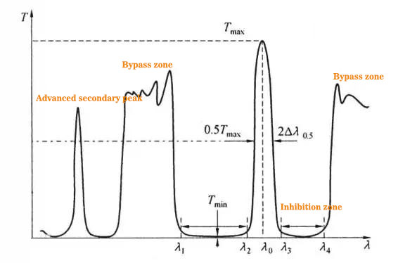
The nearby spectral transmission area is called the pass band of the filter. Usually, there are cut-off areas on both sides, and there may be a bypass band around the cut-off area. It is usually necessary to eliminate the bypass band with colored glass, absorption film or cut-off filter.
The main characteristic parameters of bandpass filter are:
① λ 0: center wavelength, also known as peak wavelength;
②Tmax: λ 0: transmittance at;
③2 Δλ 0.5: half width, which is the wavelength width of the passband where the transmission peak is half of the peak;
④2 Δλ 0.1: decimal width, which is the wavelength width of the passband where the transmission peak is 10% of the peak;
⑤2 Δλ 0.1/2 Δλ 0.5: waveform coefficient, which represents the degree of rectangular passband;
⑥2 Δλ 0.5/ λ Relative width: HW, sometimes half;
⑦ Tmin: minimum transmittance of suppression band, i.e. background transmittance;
⑧ Tmin / Tmax: inhibition rate;
⑨ λ 3- λ 4: Long wave cut-off range;
⑩ λ 1- λ 2: Short wave cut-off range.
According to the spectral characteristics, the band-pass filter can be divided into narrow-band filter and wide-band filter, but this division has no clear boundary. Generally, the filter with a relative half width of no less than 20% is called wide-band filter.
About broadband filter
Broadband filters can usually be combined with short wave pass and long wave pass filters. Considering the absorption characteristics of the film, some short wave pass or long wave pass filters can be used as broadband filters. The cut-off filter film system can be plated on different substrates. Several cut-off filters with different cut-off wavelengths can form a set of broadband filters with different half widths and peak wavelengths. Generally, the broadband filters formed in this way are not suitable for imaging systems, because multiple reflections between the film systems may cause ghost images. In order to eliminate ghost image, the whole thin-film filter must be plated on the same side of the substrate. The most effective design method is still to adopt symmetrical periodic film system.
When the symmetrical periodic film system is adopted, the equivalent single-layer film can be used to represent the short wave pass film system and the long wave pass film system, so there are three interfaces that need to be matched. If a and B represent two equivalent films, in which B is close to the substrate, the matching film layer needs to be considered between the substrate and B, B and a, and a and the incident medium Film matching can generally meet the requirements.
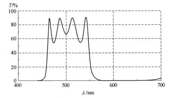
Some multi half wave filter film systems (i.e. film systems containing multiple half wave layers) can also form broadband filters, such as all dielectric four half wave filters: 1.0|h2lh2lh2lh2lh2lh1.52, where NH = 2.35, NL = 1.38, λ 0 = 500nm, its relative half width is 2 Δλ 0.5/ λ 0 = 0.20, and the spectral curve is shown in the figure below.
About narrow band filter
It is very difficult to synthesize narrow-band filter with long wave pass filter and short wave pass filter. Because it is difficult to control the cut-off wavelength, central wavelength and half width when making film, the narrow-band filter is usually designed with Fabry Perot interferometer (F-P interferometer or F-P etalon for short), and its design principle is completely different from other film systems.
According to the relevant knowledge of physical optics, the F-P interferometer is composed of two parallel reflection plates with high reflectivity and an interval of D. as shown in Fig. 2, if the air layer between the parallel reflection plates is replaced by a dielectric layer and a high reflection film is plated on both sides of the dielectric layer, a film system with spectral properties of the F-P interferometer can be obtained.
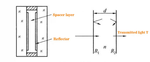
According to the theory of multi beam interference, the transmittance through the F-P etalon is
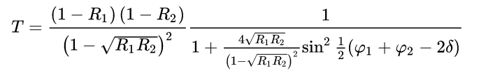
Where R1 and R2 are the reflectance of the two reflective films; φ 1 and φ 2 is the reflection phase shift of the reflection film; δ= 2πnd/ λ Is the phase thickness of the spacer.
order 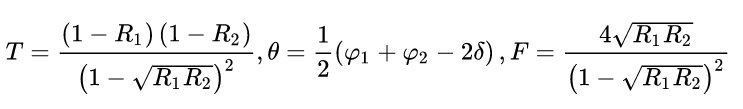
, available 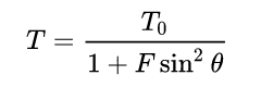
The characteristic of the formula is that the phase relationship and amplitude relationship can be studied separately, t0( λ) And F( λ) It only depends on the reflectivity of the two reflective film systems, and the factor sin ²θ It only depends on the reflection phase shift and spacer thickness of the two reflection film systems.
Application of bandpass filter
Application of broadband filter
In the practical application of optical engineering, not all places that need bandpass filters want the narrower the passband, the better, and some need broadband filters. For example, the automatic dimming mask for welding protection requires a band-pass filter that is transparent to visible light and cut off the depth of ultraviolet and infrared. Its application characteristics are as follows:
(1) Performance requirements of strong light protection filter
① Ultraviolet and infrared ray isolation: the transmittance of ultraviolet rays with wavelength of 200-380nm and infrared rays greater than 700nm is less than 3 * 10-4.
② Visible light transparency: color visible light transparent band with any wavelength between 480nm-600nm, bandwidth of 50-120nm and central transmittance of not less than 50% (transmission colors can be blue-green, dark green, emerald green, yellow green, yellow and orange).
(2) Induced filter film system
Due to the wide ultraviolet and infrared bands and deep cutoff, only metal induced filter film system can be realized. The main measures taken in the design are:
① There is no need for narrow passband here. Three layers of metal film can be selected, which can not only increase the width of passband, but also deepen the cutoff.
② Using the high refractive index layer as the spacer between the metal layers is conducive to suppress the short wave transmission sub peak in the ultraviolet region.
③ The passband waveform can be adjusted by adjusting the proportion of metal layer thickness.
It can be seen from the figure that changing the total thickness of metal film can change the passband transmittance and cut-off band depth; By adjusting the thickness of the metal film, the passband waveform will be changed.

Application of narrow band filter
For a long time, F-P interference film system, as the only way to obtain narrow-band pass filter, has been widely used in optical band. Especially in recent years, in the DWDM (dense wavelength division multiplexing) technology of optical fiber communication, F-P interferometric optical ultra-narrow band filter is used to expand the channel capacity of a single optical fiber, raising the application and manufacturing technology level of optical ultra-narrow band filter to a new level.
(1) Ultra narrow band filter used in DWDM system of optical fiber communication
In addition to the characteristics of good thermal stability, low insertion loss and low polarization related loss, the ultra narrow band filter applied to optical fiber communication DWDM system must also have rectangular passband, small passband ripple and high suppression ratio in order to correctly extract each carrier from a beam of light containing multiple wavelengths at the transmission light terminal without crosstalk.
(2) Optical comb filter (interleaver)
Optical comb filtering technology is a technology that separates a column of frequencies into Δ The optical signal of F is divided into two columns with a frequency interval of 2 Δ F optical signal and optical filtering technology output from two channels respectively.
End