Understanding optical parameters
In the design and production process of components or systems, the use of optical parameter specifications can make the components or systems accurately meet specific performance requirements. Optical parameter specifications are useful for two reasons: first, they can specify acceptable key parameter limits that determine system performance; Second, they can determine the amount of resources (i.e. time and cost) that should be spent on production.
Too low or too high parameter specification of optical system will affect its performance, resulting in unnecessary waste of resources. If all necessary parameters are not set correctly, the specification will be too low and the performance will be reduced. If the system parameters are defined too strictly without considering any changes in optical or mechanical requirements, the specification will be too high, which will increase the cost and production difficulty.
In order to understand optical specifications, it is very important to first understand their meaning. In order to simplify the increasing number of numbers, please consider using * common production specifications, surface specifications and material specifications for lenses, mirrors and window chips. Filters, polarizers, prisms, spectroscopes, gratings and optical fibers also have many such optical specifications, so understanding * common specifications will provide * a solid foundation for you to understand the specifications of almost all optical products.
Production specification
Diameter tolerance
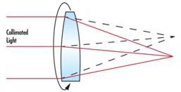
The diameter tolerance of circular optical elements provides an acceptable range of diameter values. This production specification will vary according to the technical level and ability of some optical processing companies making optical products. Although the diameter tolerance will not have any impact on the optical performance of the optical product itself, it is a very important mechanical tolerance that you must consider if you want to install the optical product on any kind of holder. For example, if the diameter of the lens deviates from its nominal value, it is possible to deviate the mechanical axis in the installed assembly from the optical axis, resulting in the eccentricity of the light (as shown in the figure). Generally, the production tolerance of diameter is: + 0.00 / – 0.10 mm, which means general quality, + 0.00 / – 0.050 mm means precision quality, and + 0.000 / – 0.010 mm means high quality
Center thickness tolerance
The central thickness of an optical element (* typically a lens), which measures the material thickness of the central part of the optical element. The central thickness is measured by the mechanical axis of the lens, which is defined as the axis between the outer edges of the lens. The change of lens center thickness will affect the optical performance, because the center thickness and its radius of curvature will determine the optical path length of light passing through the lens. Generally, the production tolerance of center thickness is + / – 0.20 mm for general quality, + / – 0.050 mm for precision quality and + / – 0.010 mm for high quality
Radius of curvature
The radius of curvature refers to the distance between the vertex of the optical element and the center of curvature. The radius can be positive, zero, or negative, depending on whether the surface is convex, planar, or concave. If the curvature radius value is known, the optical path length of light passing through the lens or mirror can be determined, and it also plays an important role in determining the surface power. The production tolerance for radius of curvature is usually + / – 0.5, but it can also be as low as + / – 0.1% in precise applications or + / – 0.01% in cases where very high quality is required.
H3 > Center
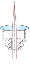
The center of the lens, also known as centripetality or eccentricity, is based on the beam deviation δ (equation 1). Once the beam deviation is given, the wedge angle w can be calculated by a simple relationship (equation 2). The eccentricity of the lens is the physical deviation distance between the mechanical axis and the optical axis. The mechanical axis of the lens is only the geometric axis of the lens, which is defined by its external cylindrical surface. The optical axis of the lens is defined by the optical surface, which is the line connecting the curvature center of each surface. To perform the centripetality test, place the lens in a teacup and press it. The pressure applied to the lens will automatically gather at the center of curvature of the first surface in the center of the cup, and the center will also be aligned with the rotation axis (as shown in the figure). The parallel light emitted along this rotation axis will pass through the lens and reach the focus of the rear focal plane. When the lens rotates with the rotation of the tea cup, any eccentricity in the lens will disperse the focused beam and form a radius of Δ Circle track of (as shown in the figure).
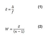
Where W is the wedge angle, usually reported as minutes of arc, and N is the refractive index.
Parallelism
Parallelism describes the relationship between two parallel surfaces. It is useful when specifying elements such as window and polarizer, in which parallel surfaces are ideal planes to improve system performance because they can * greatly reduce distortion, otherwise the distortion will reduce the quality of image or light. Typically, this tolerance ranges from 5 arc minutes to a few arc seconds.
Angular tolerance
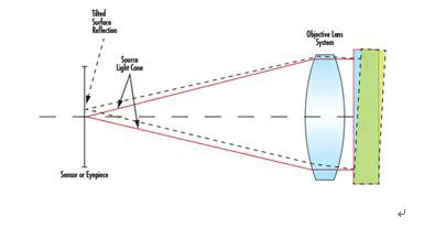
In prisms, spectroscopes and other components, the angle between the surfaces has an important impact on the performance of optical products. The angular tolerance is usually measured using a collimating telescope assembly whose light source system emits parallel light. The collimating telescope will rotate around the surface of the optical product until the generated Fresnel reflection returns to the surface, producing a light spot on the top of the detected surface. This verifies that the parallel beam is incident exactly perpendicular to the surface. Then, the whole collimating telescope assembly will rotate around the optical product to the next optical surface, and the process will be repeated. Figure 3 shows the general collimating telescope setup for measuring angular tolerances. The angular difference between the two measurement positions can be used to calculate the tolerance of the two optical surfaces. The range of angular tolerance can be reduced from a few arc minutes to a few arc seconds.
Chamfer
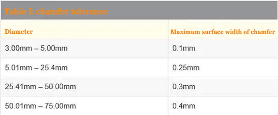
Glass corners are very fragile, so it is important to protect them when handling or installing components. A common way to protect these glass corners is to chamfer these edges obliquely. Chamfering can be used as a protective groove to prevent notches at the edge. They are defined by the width and angle of their surface (as shown in the figure).
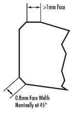
The * common cutting angle of the chamfer is 45 °, and the surface width is determined by the diameter of the optical product. Optical products with a diameter of less than 3.00mm (such as microlenses or micro prisms) usually do not need to be chamfered because edge notches are likely to occur in the cutting process. It should be noted that for very small radius of curvature, for example, when the diameter of the lens is greater than or equal to 0.85 x radius of curvature, it is not necessary to cut into chamfer, because there is a large angle between the surface and edge of the lens. For all other diameters, table 1 provides * large surface widths.
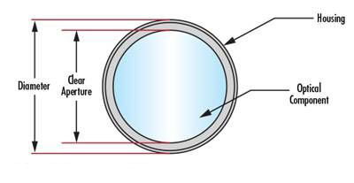
Luminous aperture
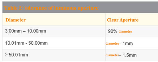
Optical aperture refers to the diameter of optical elements or the size of optical elements that must meet various specifications. The manufacturer cannot ensure that the optical products meet the specified specifications except for the optical aperture. Due to the limitation of production, it is actually impossible to produce a luminous aperture exactly equal to the diameter or length multiplied by the width of the optical product. Table 2 shows the general luminous aperture of the lens.
Surface specification
surface quality
The quality of optical surface is used to measure the surface characteristics of optical products, and covers some defects such as scratches and pits. Most of these surface defects are purely surface defects and will not have a great impact on the system performance, although they may cause a slight decline in the luminous flux of the system and a more subtle scattering of scattered light. However, some surfaces are more sensitive to these effects, such as: (1) the surface of the image plane because these defects will produce focus, and (2) the surface with high power level because these defects will increase energy absorption and destroy optical products. Surface quality * the commonly used specifications are the scratch and pit specifications described by mil-prf-13830b. The scratch name is determined by comparing the scratch on the surface with a series of standard scratches provided under controlled lighting conditions. Therefore, the scratch name does not describe the actual scratch, but compares it with the standard scratch according to the mil specification. However, the pit name is directly related to the point or small pit on the surface. The accuracy is calculated by dividing the diameter of the pit by 10 to 40 microns, which is usually regarded as the point with a high quality between 10 and 40 microns.
Surface flatness
p> Surface flatness is a type of specification for measuring surface accuracy. It is used to measure the deviation of planes such as mirrors, window sheets, prisms or flat mirrors. You can measure this deviation using an optical flat crystal, which is a high-quality, high-precision reference plane used to compare the smoothness of the specimen. When the plane of the tested optical product is placed against the optical flat crystal, stripes will appear, and their shape represents the surface smoothness of the tested optical product. If these fringes are equally spaced and are parallel straight lines, the optical surface to be detected is at least as flat as the reference optical flat crystal. If the stripe is curved, the number of stripes between two dashed lines (one tangent to the midpoint of the stripe and the other passing through the endpoint of the same stripe) indicates an error in smoothness. The deviation of smoothness is usually based on the ripple value( λ) They are composed of test sources with multiple wavelengths. One stripe corresponds to ½ Wavelength. The smoothness is 1 λ, Indicates the general quality level; Smoothness is λ/ 4, it indicates the accurate quality level; Smoothness is λ/ 20 indicates the quality level of high precision.
Aperture number
Aperture number is a type of specification for measuring surface accuracy. It is suitable for curved optical surfaces or surfaces with power. The aperture number test is similar to the flatness test, which compares the surface with a reference surface with a high collimation radius of curvature. Using the same interference principle generated by the gap between the two surfaces, the interference pattern of the fringe is used to describe the deviation between the test surface and the reference surface. The deviation from the reference will produce a series of rings called Newton rings. The more rings present, the greater the deviation. The number of dark or bright rings, rather than the total number of dark and bright rings, is equal to twice the wavelength error.
Irregularity
Irregularity is a type of specification for measuring surface accuracy. It describes the deviation between the surface shape and the reference surface shape. Irregularity is measured in the same way as the number of apertures. Regularity refers to the spherical circular stripe formed by comparing the test surface with the reference surface. When the aperture number of the surface exceeds 5 stripes, it will be difficult to detect small irregular shapes with less than 1 stripe. Therefore, it is common practice to specify the ratio of the number of apertures to the irregularity of the surface, so that it is about 5:1. For more details on optical flat crystals and fringe patterns that describe the flatness, aperture number and irregularity of the test, see “optical flat crystals”.
Surface processing
Surface machining, also known as surface roughness, is used to measure some small irregularities of the surface. They are usually an adverse consequence of the polishing process. Rough surfaces tend to be more wear-resistant than smooth surfaces and may not be suitable for some applications, especially in laser or overheated environments, because there may be subtle cracks or defects at the nucleation site. The production tolerance of surface machining is 50 Å RMS for general quality, 20 Å RMS for accurate quality and 5 Å RMS for high quality.
Material specification
Refractive index
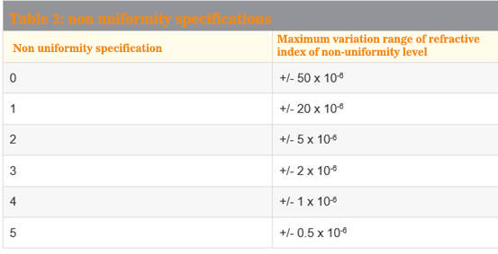
The refractive index of a medium refers to the ratio of the speed of light in vacuum to the speed of light in the medium. The refractive index range of glass is generally between 1.4-4.0. Compared with the glass optimized for infrared, the refractive index range of visual glass is smaller. For example, n-bk7 (a general-purpose visual glass) has a refractive index of 1.517, while germanium (a general-purpose infrared glass) has a refractive index of 4.003. For more information about infrared materials, see “the right materials for infrared (IR) applications”. The refractive index of optical glass is an important property, because the power of optical surface is obtained from the difference between the radius of curvature of the surface and the refractive index of the medium on either side of the surface. The non-uniformity specified by the glass manufacturer refers to the change in the refractive index of the glass. Nonuniformity is specified according to different grades, in which grade and nonuniformity are opposite to each other, and the nonuniformity will decrease with the increase of grade (Table 3).
Dispersion coefficient
Another material property of glass is the dispersion coefficient, which is used to quantify the amount of dispersion presented by glass. It is the refractive index of the material at the wavelengths of F (486.1 nm), D (587.6 nm) and C (656.3 nm) (equation 3).
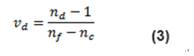
Dispersion coefficient values typically range from 25 to 65. When the dispersion coefficient of glass is greater than 55 (less dispersion), the glass will be regarded as crown glass, while those with dispersion coefficient less than 50 (more dispersion) will be regarded as flint glass. Due to dispersion, the refractive index of glass will vary with wavelength. The significant result of dispersion is that the focal length of the system will vary slightly with different light wavelengths. For more details on important material specifications such as refractive index and dispersion coefficient, see “optical glass”. H3 > laser damage threshold
Laser damage threshold refers to the amount of * high laser power that the surface of each area can withstand before laser damage. Both pulsed laser and continuous wave (CW) laser have corresponding laser damage thresholds. Laser damage threshold is a very important material specification for mirrors because they are used with laser products rather than any other optical products. However, any laser grade optical products will provide threshold. For example, consider Ti: sapphire laser mirrors with a damage rating threshold of 0.5 J / cm2 @ 150 femtosecond pulses and 100 kW / cm2 CW. This shows that the energy density of the high repetition femtosecond pulse laser that the mirror can withstand per square centimeter is 0.5j, or the energy density of the high-power CW laser that can withstand per square centimeter is 100kW. If the laser beam is concentrated in a smaller area,
Measures must be considered to ensure that the overall threshold does not exceed the specified value. Although there are a range of other production specifications, surface specifications and material specifications, confusion can be significantly avoided if you understand * common optical specifications. Lens, reflector, window, filter, polarizer, prism, spectroscope, grating and optical fiber share various properties. Therefore, understanding the relationship between them and how they will affect the overall system performance will help you choose * good components to integrate into optical, imaging or optoelectronic applications.
End